|
Power Factor Control Relay CXPLUS
6-12-14 Steps Common Point or Volt Free
General Features
The CXPLUS incorporates all the technical features PFC engineers worldwide have been asking for over recent years. The target power factor is set by the user and the CXPLUS will select the most suitable capacitor size using the best fit principle. This allows the use of large and small capacitor steps to match the reactive demand. The most important influence on PFC in the last decade has been the ever increasing effect of harmonic voltages and currents resulting from variable speed drives, UPS supplies, switched mode power supplies and rectifiers etc. All of these devices are generating harmonic voltages which will damage and overload PFC capacitors if they are not limited by fitting harmonic detuning reactors to each capacitor. The CXPLUS detects harmonic voltages and alarms can be set to pre-selected threshold levels THDU.
What do we mean by Power Factor Today ?
Many articles have been written on the true meaning of the term 'Power Factor'. No longer is it true to say that the power factor is measured by the time difference between the current and voltage waves crossing the zero point. This is true for the 'fundamental 50 or 60 hz power factor' known as Cosphi. The true power factor is calculated from the values of kW/kVA otherwise known as the true RMS power factor. The CXPLUS evaluates both power factors and gives display of the two values. Comparison of these two values enables the consumer to see the effect of harmonic voltages and currents on his system. All power capacitors are given a rated value in kvar based on their output at 50 or 60hz. Therefore the CXPLUS uses Cosphi to switch capacitors in and out according to reactive power demand on the system.
Modbus Data Output
Todays energy management systems often demand output by Modbus to the BMS ( Business management System ) the PLC controller., or the MINISCADA interface. A Modbus data output module can be added to the CXPLUS by fixing on the back of the relay . For more details see  MODBUS BOLT ON BACK MODBUS BOLT ON BACK
Ambient temperature and Setting Alarms etc.
The ambient air temperature of PFC cubicle has a strong effect on the capacitor lifetime. The CXPLUS is fitted with an over temperature varistor so as to give visual a alarm and if so required to switch off capacitors one by one once this temperature threshold has been reached . This low cost option also allows automatic start up of the ventilation fan in the cubicle. The temperature monitor shows the actual and highest ambient temperature reached.
Menu 504 in the expert menu will allow the consumer to disconnect capacitors if the THDU level rises above the selected setting. The default setting is 5%
The relay has a large selection of alarm settings and the control menu is divided in two sections:
Menu 100 The general non professional menu. This enables the works engineer to programme the relay for step switch time, CT ratio, target power factor, output of each exit relay AUTO -F ON (permanently on) F-OFF ( permanently off) HOLD .
The OPh feature tells the user how many hours the relay has been in service for since the last reset. An alarm can be set once the pre-selected number of hours has elapsed. A very useful feature to remind the user that the equipment is due for a service.
The MANUAL menu allows the switching of capacitor steps by hand especially important when commissioning for the first time on a lightly loaded installation.
The INFO menu tells the user the kvar output of each step in comparison with its initial value, the number of times each step contactor has operated and whether each step is AUTO Alarm ( for ventilation fan contact ) - Permanently ON or Permanently OFF.
The Expert Menus 200-600 allow the professional to select threshold values for alarms etc. The functions of all the menus are clearly explained in the CXPLUS operating instructions issued with each relay. The professional user receives instructions in the handbook to show how to enter these professional settings so as to inhibit unauthorised ' meddling ' with the relay settings.
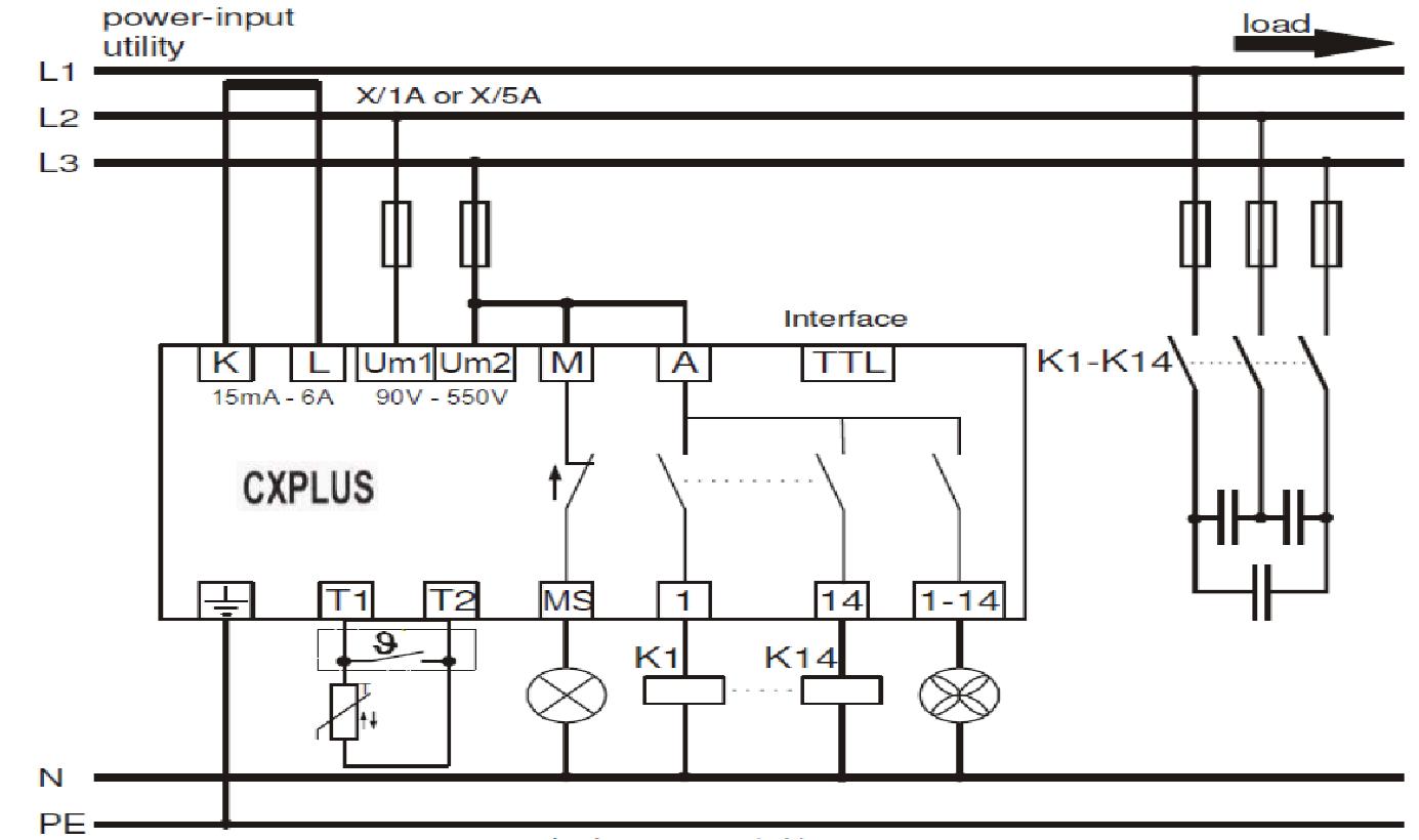
The CXPLUS follows the normal principle of having 90° phase-shift between voltage and current at unity power factor so that the CT is normally on a different phase to the two phases used for measurement and power supply to the relay Um1-Um2. If this connection is not possible or single phase measurement is used , there is a phase offset function ( Menu 206 ) which allows the CT to be corrected to any phase, with various phase angle offsets. If the CT is connected the wrong way round in error this can be rectified on menu 206.
The CXPLUS is powered by switch mode power supply and accepts any voltage in the range 90-550V 50/60Hz. Previous relays needed voltage transformers for each value these are no longer needed.
VENTILATION CONTROL:
The CXPLUS has up to 14 steps. Any one of these steps can be used as a temperature alarm switch to start up a fan.. Simply set the step exit relay selected for fan control to AL
WIRING DIAGRAM
|
Standard Features
Scroll through voltage harmonics 3rd up to 19th
Modbus output if required
Up to 14 steps. Common stock sizes 6 step and 12 step
Volt free version available
No more voltage transformers. The CXPLUS accepts any voltage from 90 550V AC
Backlit LCD display
Ambient temperature recording and max temp data logged. Alarm feature can be actuated from measured temperature
Self commissioning using best fit principle
Scroll down Multimeter of all measured values including Voltage and THDU
Rapid Switch facility down to 1 sec. Per step with discharge timer setting to ensure capacitor must discharge before being re-energised
Counter for each closing of contactor
Data Log of kvar output of each step and % comparison with initial kvar value
Ventilation from control from any one of the exit relays
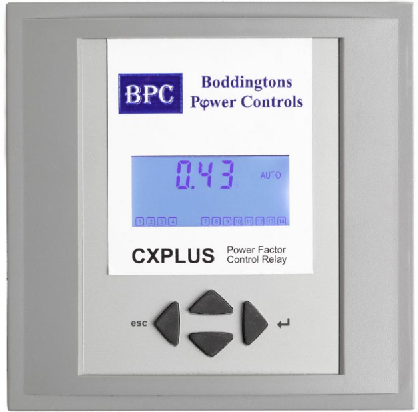
Display
A high contrast LCD backlit display shows all values including steps in or out of circuit. On initial power up the relay will show the following scroll down values:
Phase-phase voltage
Phase-neutral voltage
Phase Amps
3 phase kW (assumes balanced load)
3 phase kvar to reach target PF
3 phase total kvar
3 phase kVA
THDU % - Total Voltage Harmonic Distortion as % of fundamental
3-5-7-9-11-13-15-17-19 voltage harmonics, each value separately as % of fundamental voltage
Cosphi fundamental power factor
PF True RMS power factor
APF Average time RMS power factor since relay commissioned
F Frequency of supply
T-LO -Ambient cubicle temperature (if temp indicator optional extra selected)
THI Max Ambient temp recorded(if temp indicator optional extra selected)
0ph Hours the relay has been in service since last reset .This value can be set to trigger an alarm
MONITORING AND ALARM FUNCTIONS
The CXPLUS allows the following to be monitored and if threshold values are exceeded alarm contacts M will close:
Low or high voltage switch off if supply voltage is outside nominal limit ( default is 10% ). Low voltage can cause chattering contractors and reduced contactor life
Number of operations of each contactor
Over temp switch off
Recognition of defective capacitors
Failure to reach target Power Factor Alarm and loss of power alarm
Number of hours since last service Alarm can be set to required number of hours
Fan start up if ambient temp values exceeded
Download the CXPLUS Instruction Manual
Download the CXPLUS Expert's guide
|